Scope the decision
Define the engineering question, available inputs and acceptance criteria.
Engineering intelligence · Physical evidence
From CATIA-connected AI agents to CAD-native topology optimization, production-line vision, multiphysics simulation and extreme-environment testing. Five capabilities connect the design decision to physical evidence.
Illustrative schematic. Not a simulation result or manufactured component.
From the technical profile
Specific capabilities. Reported measurements. Follow each figure to its source context and application.
Topology optimization
≥10×Profile-reported computational efficiency improvement for complex 3D structures.
Technical details ↗Vision inspection
15 m/sReported for the nonwoven production-line inspection case.
Technical details ↗FEA simulation
15High-performance computational platform listed in the profile.
Technical details ↗Physical validation
1000 kNTension, compression, bending and shear; extended stroke accommodates environmental testing.
Technical details ↗Capabilities
Explore the technology, source-reported performance, reference configurations and application scenarios.
Custom AI agents connect CATIA parametric design, RAG knowledge bases and MCP/API tools to real engineering workflows, with private or edge deployment and ongoing support.
Optimize CAD-linked feature shape, position and orientation, with isogeometric analysis for stiffened plates and shells. The profile reports ≥90% fewer design variables and ≥10× computational efficiency for complex 3D optimization.
Custom optics, mechanical integration, algorithms and software for production-line inspection. The nonwoven case reports up to 15 m/s, a minimum defect area of 0.25 mm² and a missed-defect rate below 0.1%.
Static, dynamic, nonlinear and multiphysics analysis, including fatigue, crack growth, thermal stress and fluid–structure interaction. The profile lists 15 networked CAE workstations and six simulation software platforms.
Prototype machining and static, dynamic and extreme-environment testing through a university-supported laboratory platform, including two five-axis machining centers, 1000 kN materials testing and a listed −80 to 1600°C component chamber.
Explore how it works
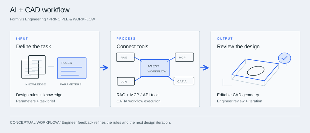
Principle & workflow

Start with a fixture or repeatable part family. Supply the design rules, parameter ranges and reference knowledge that define acceptable output.
The agent retrieves relevant knowledge and uses authorized tools to carry out defined engineering steps. The integration connects the model with the actual CAD or business system.
Review native geometry, parameter values and rule compliance. Feed corrections back into the workflow before extending it to more designs.
The way we work
Define the engineering question, available inputs and acceptance criteria.
Select a representative workflow, component or material sample.
Compare output quality, limitations and engineering effort.
Choose integration, a further study or a physical validation program.
Technical notes
The next step