Networked CAE workstations
High-performance computational platform listed in the profile.
ENGINEERING ANALYSIS Structural, failure & multiphysics analysis
Static, dynamic, nonlinear and multiphysics analysis, including fatigue, crack growth, thermal stress and fluid–structure interaction. The profile lists 15 networked CAE workstations and six simulation software platforms.
Discuss a simulation challenge ↗Technical highlights
Reported capabilities and figures from the supplied technical profile, with their application context.
High-performance computational platform listed in the profile.
Abaqus, Ansys, Ansys Fluent, Ansys LS-DYNA, Zencrack and Optimus.
Linear elasticity, nonlinear response, modal, harmonic and transient-impact analysis.
Thermal stress/deformation and fluid pressure interacting with structures.
Source: Technical Capabilities — External Presentation · 2026-08 · pp. 8. Source and scope ↓
Engineering overview
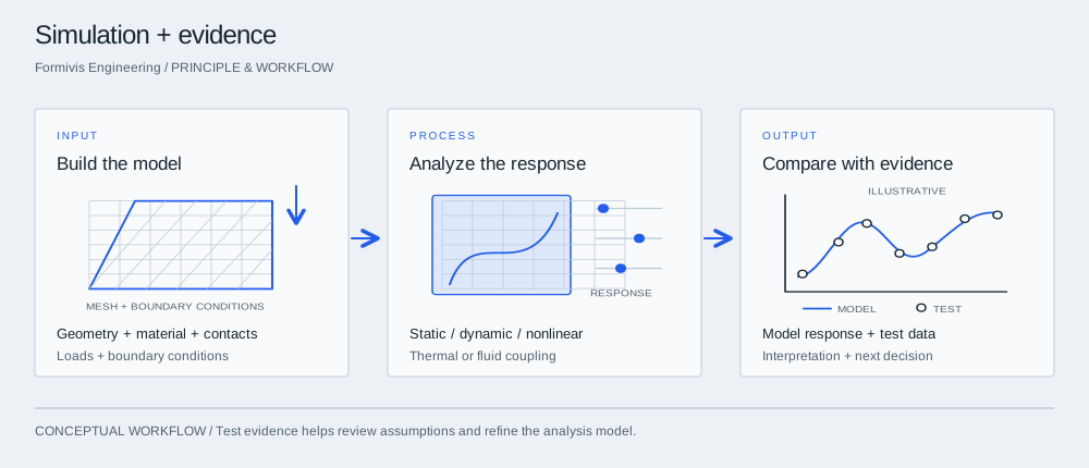
Simulation is organized around explaining the physical behavior of a product under its service conditions. Formivis combines structural response, failure mechanisms and coupled physics, using physical experimental data as the intended final validation reference.
Principle & workflow

Define the physical question and the inputs that control it. Build a model with traceable units, material properties, contacts and constraints.
Choose the analysis that matches the question: structural response, fatigue, crack growth, creep, thermal stress or fluid–structure interaction.
Compare modeled quantities with available physical measurements, review sensitivity and explain what the results mean for a design change or validation plan.
Analysis scope
Analyze linear-elastic response, geometric and material nonlinearity, modal behavior, harmonic response and transient impact.
Failure analysis
Investigate contact, fatigue life, crack propagation, plastic deformation and creep to connect initial damage with the eventual failure mechanism.
Multiphysics
Model thermal–structural effects such as thermal stress and deformation, and fluid–structure interaction where fluid pressure changes structural response.
| Platform | Listed scope |
|---|---|
| Abaqus | Finite element structural and coupled-field analysis. |
| Ansys | General structural and dynamic analysis. |
| Ansys Fluent | Fluid and flow-field analysis. |
| Ansys LS-DYNA | Transient impact and dynamic analysis. |
| Zencrack | Crack propagation, fatigue, creep and damage simulation. |
| Optimus | Multidisciplinary optimization and design integration. |
| 15 networked CAE workstations | High-performance computing for engineering analysis. |
Applications & value
Application context
Compare displacement, stiffness and stress concentration to inform a geometry or material decision.
Profile illustration
The profile illustrates laser melt-through simulation as an example of a coupled thermal and structural analysis topic.
Application context
Use fatigue, crack-growth, contact and creep studies to explain a failure or scope a follow-up physical test.
Who it's for
R&D and reliability teams investigating design decisions, product failures or simulation-to-test differences.
Bring the application, representative inputs and acceptance criteria. We will connect the relevant technology and platform to a defined engineering deliverable.
Before we begin
The profile lists static and dynamic analysis, geometric/material nonlinearity, modal and harmonic response, transient impact, contact, fatigue, crack growth, plasticity and creep, plus thermal–structural and fluid–structure coupling.
Abaqus, Ansys, Ansys Fluent, Ansys LS-DYNA, Zencrack and Optimus, supported by 15 networked high-performance CAE workstations.
The stated method uses physical experimental data as the final validation reference. Available measurements, comparison quantities and any additional testing are identified in the project plan.
The next step