ENGINEERING METHODS
FEA capabilities: from failure mechanisms to physical evidence
Principle & workflow
From physical assumptions to a design decision
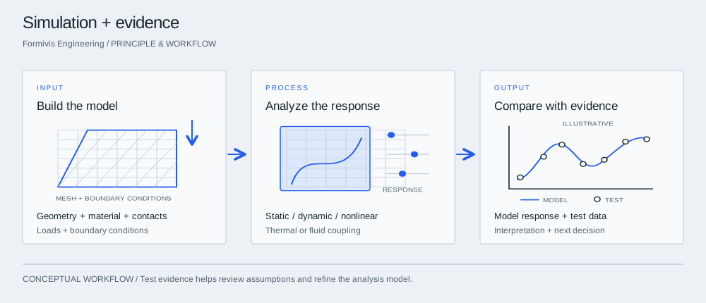

InputBuild the model
Define the physical question and the inputs that control it. Build a model with traceable units, material properties, contacts and constraints.
ProcessAnalyze the response
Choose the analysis that matches the question: structural response, fatigue, crack growth, creep, thermal stress or fluid–structure interaction.
OutputCompare with evidence
Compare modeled quantities with available physical measurements, review sensitivity and explain what the results mean for a design change or validation plan.
The analysis capability
The profile lists linear and nonlinear static/dynamic analysis, modal and harmonic response, transient impact, contact, fatigue life, crack propagation, plasticity and creep. Thermal–structural and fluid–structure coupling address interacting physical effects.
The listed computational platform
The platform includes 15 networked high-performance CAE workstations and Abaqus, Ansys, Ansys Fluent, Ansys LS-DYNA, Zencrack and Optimus. The stated working method treats physical experimental data as the final validation reference; a project must identify which measurements support its conclusions.
Write the decision first
State which choice the study supports: a design change, an explanation of failure or a test plan. Specify what uncertainty is acceptable for that decision. This determines which model details matter.
Make assumptions visible
Record units, materials, contacts, loads and constraints. Note which inputs come from measurement, supplier data or engineering estimates. Revisit the assumptions that materially change the conclusion.
Connect computation and evidence
Ask how mesh sensitivity, solver settings and physical measurements will be reviewed. If there is no test evidence, label the result accordingly. Analysis can support a decision without being presented as a certified or physically validated outcome.
Deliver something another engineer can review
Keep input provenance, model versions and result interpretation together. A handoff should explain the comparison and its limitations, not only present the preferred image.
Take into the discussion
- Decision and acceptance criteria
- Traceable inputs and units
- Sensitivity and convergence review
- Available physical evidence
- Limitations and next validation step
Technical questions
Which types of FEA are covered?
The profile lists static and dynamic analysis, geometric/material nonlinearity, modal and harmonic response, transient impact, contact, fatigue, crack growth, plasticity and creep, plus thermal–structural and fluid–structure coupling.
Which software platforms are listed?
Abaqus, Ansys, Ansys Fluent, Ansys LS-DYNA, Zencrack and Optimus, supported by 15 networked high-performance CAE workstations.
How does the analysis connect to testing?
The stated method uses physical experimental data as the final validation reference. Available measurements, comparison quantities and any additional testing are identified in the project plan.