BUILD & TEST
Machining and extreme-environment testing: platform and scope
Principle & workflow
From a machined specimen to measured response
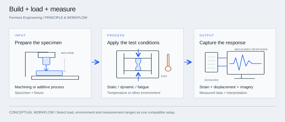

InputPrepare the specimen
Connect the drawing, material and specimen geometry to the machining route. Prepare the fixture and measurement locations as part of the test plan.
ProcessApply the test conditions
Choose a compatible combination of loading and environmental equipment. Individual maximum ratings do not mean all maximum conditions can be applied together.
OutputCapture the response
Use appropriate optical or bonded strain measurement, laser displacement, vibration signals or high-speed imagery to characterize the response and compare it with the target.
Machine the specimen and fixture
Combine five-axis machining, sheet-metal bending, industrial 3D printing and wire EDM with the specimen and fixture requirements of the test plan.
Characterize static and dynamic behavior
Connect materials testing, fatigue, vibration, creep and dynamic mechanical analysis to the load cases used in design and simulation.
Capture response in demanding conditions
Pair environmental equipment with optical or bonded strain measurement, laser displacement and high-speed imaging as appropriate for the specific test configuration.
Reported figures and their scope
Five-axis machining centers: 2. Listed platform inventory for precision metal machining. Universal materials testing: 1000 kN. Tension, compression, bending and shear; extended stroke accommodates environmental testing. Component chamber temperature range: −80 to 1600°C. Listed for the component static-environment chamber; not the range of every test system. Impact tester energy: 150–300 J. Listed equipment range for dynamic impact loading.
Prototype-to-test development
Machine specimens and fixtures, define measurement channels and compare measured response with the original engineering assumptions.
Materials in extreme environments
Study temperature-dependent response, fatigue or creep using an agreed specimen geometry and compatible equipment combination.
Equipment vibration and durability
Evaluate structural vibration and fatigue for transport equipment, bearings, mining machinery and civil structures within the selected platform’s scope.
Project interpretation
The profile does not establish laboratory accreditation or certified-report scope. Listed ratings are equipment-specific and do not imply every maximum is available simultaneously.
Take into the discussion
- Drawings, material requirements and specimen quantities
- Test objectives, conditions and measurement needs
- Required report use, schedule and acceptance criteria
Technical questions
What machining equipment is listed?
The profile lists two five-axis machining centers, two stainless-steel bending machines, one industrial 3D printer, one wire EDM, two bench drills, one CNC tapping machine, one CNC machine tool, one CNC mill, one welder and two grinders.
Does −80 to 1600°C apply to every test?
No. That range is attached to the component static-environment chamber. Temperature, load, frequency and specimen dimensions must be matched to a compatible test setup.
Does the 18-tonne vibration-table figure mean payload?
The source lists 18 tonnes but does not state the force/load convention. It must not be treated as a confirmed 18-tonne payload specification.