TOPOLOGY OPTIMIZATION · ROBOTICS
How to Benchmark Topology Optimization for a Robotic Bracket or Lightweight Structure
Principle & workflow
From design space to useful CAD geometry
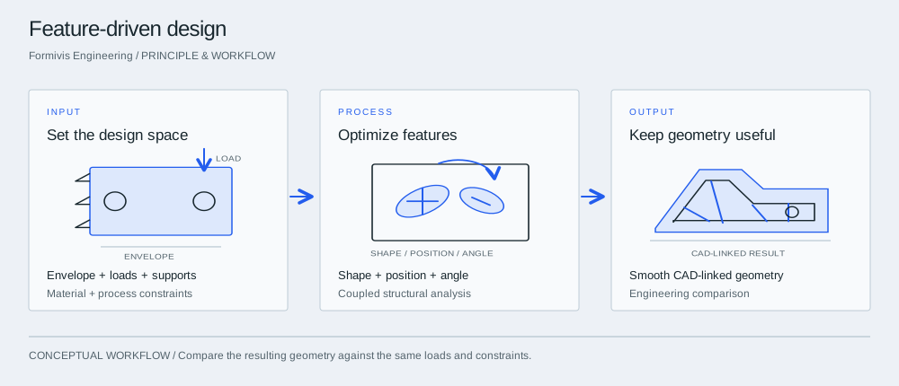

InputSet the design space
Define the region where material may be placed, the applied loads and supports, and the manufacturing constraints that the design must satisfy.
ProcessOptimize features
The feature-driven method changes CAD-associated shapes, positions and angles. For stiffened shells, openings, surface form and stiffener arrangement can be considered together.
OutputKeep geometry useful
Compare structural behavior and geometry usability with the baseline. CAD-connected geometry reduces the need to reconstruct an optimization result by hand.
Choose a component with a real engineering decision
A robotic bracket, end-effector support, machine frame subcomponent or other stiffness-sensitive part can be a useful benchmark when the design space and loads are understood. Avoid selecting a demonstration part simply because it creates an attractive topology result. Define the interfaces that cannot move, the allowable design volume, material, load cases, stiffness or displacement requirements and any frequency or manufacturing constraints. The same engineering problem should be given to the baseline workflow and the candidate method so that differences in output are not created by different assumptions.
Make manufacturing constraints explicit before optimization
The acceptable geometry depends on how the part will be made. Machined, cast and additively manufactured parts may need different minimum thicknesses, tool-access zones, symmetry, draw direction or support constraints. These requirements should be recorded before the run, not added later as an informal cleanup step. A topology result that meets a structural objective but requires major redesign to satisfy the intended process should not be treated as a complete engineering outcome. The benchmark should therefore track what constraints were encoded and what manufacturing interpretation was still required after optimization.
Measure the CAD handoff
Mainstream design systems increasingly treat the handoff between faceted optimization results and editable CAD as part of the workflow. Siemens describes convergent modeling as a way to work with facet and precise geometry together. A buyer should therefore evaluate the geometry that exists after optimization: whether it can be edited, dimensioned, combined with production features and passed to downstream engineering without extensive reconstruction. Record CAD cleanup and reconstruction time separately from solver time so that a faster optimization stage does not hide a more expensive downstream task.
Add an engineering-change test
After the first acceptable result, change one requirement: move a mounting interface, change a load, add a keep-out zone or revise a thickness constraint. Then measure what must be rebuilt or re-run. Lightweight equipment rarely remains unchanged through a development program. A workflow that preserves engineering intent and can respond to requirement changes may be more valuable than one that produces a slightly better one-shot metric but forces repeated reconstruction. The change test is also a practical way to expose how tightly the optimization result is connected to CAD parameters and downstream analysis.
Re-analyze the geometry that would actually be released
The final validation should use the geometry that would continue through the engineering process, not only the raw optimization field. Re-run the agreed load cases and compare the final reconstructed or edited geometry with the same targets used in the baseline. If physical testing will be required, identify that step separately. Formivis reports a feature-driven, CAD-linked topology approach in its supplied profile, including company-reported efficiency results. Those figures should be treated as source-reported evidence and re-tested on the representative part before being used as a production expectation.
Use the robot duty cycle to define the bracket problem
A bracket that supports a payload on a moving robot should be assessed against the intended motions and interfaces, not just a stationary vertical force. Ask the responsible engineer to identify payload offsets, acceleration and braking cases, cable or hose loads, joint assumptions and relevant vibration conditions. Record which cases govern stiffness and which govern stress or fatigue evaluation. These are project inputs to be established with the equipment team; this guide does not prescribe universal loads or a robot safety qualification procedure.
Keep the assembly and manufacturing interfaces in the scorecard
Preserve the mounting faces, fastener access, locating features and clearance envelopes required by the assembly. If the candidate changes joint stiffness or contact assumptions, document that change before comparing the results. Compare the finished part with its baseline for interface displacement, the agreed dynamic checks, manufacturability, CAD editing effort and the next physical validation step. A lower mass alone is insufficient if it creates assembly interference or unacceptable motion at the tool interface.
Take into the discussion
- Representative part and design space
- Shared load cases and material assumptions
- Manufacturing constraints
- CAD reconstruction/editability measures
- Engineering-change and re-analysis test