STRUCTURAL DESIGN
Feature-driven topology: CAD geometry and reported efficiency
Principle & workflow
From design space to useful CAD geometry
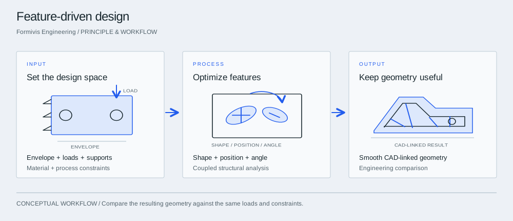

InputSet the design space
Define the region where material may be placed, the applied loads and supports, and the manufacturing constraints that the design must satisfy.
ProcessOptimize features
The feature-driven method changes CAD-associated shapes, positions and angles. For stiffened shells, openings, surface form and stiffener arrangement can be considered together.
OutputKeep geometry useful
Compare structural behavior and geometry usability with the baseline. CAD-connected geometry reduces the need to reconstruct an optimization result by hand.
Direct control of engineering features
Optimize feature shapes, positions and angles while retaining a connection to the CAD model. The value is a shorter route from an optimization result to an editable engineering geometry.
Smooth geometry for additive manufacturing
G1/G2-continuous boundaries support geometric usability and additive-manufacturing workflows. The profile claims elimination of post-processing; project review must define geometry reconstruction separately from physical finishing.
Coupled plate and shell design
Use isogeometric analysis to explore openings, surfaces and stiffener layouts together, addressing coupled choices that are difficult to optimize independently.
Reported figures and their scope
3D optimization efficiency: ≥10×. Profile-reported computational efficiency improvement for complex 3D structures. Fewer design variables: ≥90%. Reported reduction in the scale of design variables. Lower CAD-to-manufacturing handoff cost: ≥80%. Applies to the design/manufacturing interface and reconstruction work; not total product cost. Surface continuity: G1 / G2. Smooth optimized boundaries and CAD-compatible geometry. Design flexibility improvement: ≥50%. The profile describes flexibility and adaptability of the design space; this is not a structural degrees-of-freedom count. Stiffened-shell optimization efficiency: ≥5×. Reported improvement for joint optimization of openings, topology, surface form and stiffeners. Stiffened-shell analysis error: ≤1%. Profile-reported analysis accuracy for the described isogeometric method; benchmark details are not supplied.
Thermal structures and 3D channels
Explore heat-dissipation structures and integrated three-dimensional flow-channel layouts. These are illustrated application directions in the profile.
Robotics and machine tools
Study robot-joint stiffness and inertia, machine-tool columns and beds, and the distribution of material around the load path.
Lightweight transport structures
Explore stiffened aerospace panels, vehicle subframes and battery enclosures against defined load and manufacturing constraints.
Structures across industries
Potential contexts include civil structural nodes, implants and fixation parts, energy equipment, sports products and micro- or nano-scale optical structures. Suitability is assessed by application.
Project interpretation
Reported improvements come from the supplied technical profile. Baseline geometry, hardware, solver settings and sample-level benchmark records are not included; agree those conditions for a like-for-like project comparison.
Take into the discussion
- Geometry and permitted design space
- Loads, materials, boundary conditions and constraints
- Manufacturing process and baseline comparison
Technical questions
What do the ≥10× and ≥5× figures describe?
The supplied profile reports ≥10× computational efficiency for complex 3D topology optimization and ≥5× collaborative optimization efficiency for stiffened plates and shells. They describe different study scopes.
Does ≥80% mean an 80% reduction in the cost of the product?
No. The figure refers to the design-to-manufacturing interface cost associated with CAD compatibility and avoiding manual reconstruction. It is not a total manufacturing-cost or mass-reduction figure.
Which geometry variables can be optimized together?
The method works with CAD-associated feature shape, position and angle. The stiffened-shell method combines opening shape, topology, surface form and stiffener arrangement.